Justin Miller and I were asked to do an impromptu presentation on 60GHZ at the US 2019 MUM. This is what we threw together in an hour. When John Tully asks you hop to. haha! Small Download

Justin Miller and I were asked to do an impromptu presentation on 60GHZ at the US 2019 MUM. This is what we threw together in an hour. When John Tully asks you hop to. haha! Small Download

In a previous series of articles we talked about a new Cambium 550 link and the noise challenges we had. You can start your reading in Part one and Part two.
Due to the frequency challenges, we decided to upgrade the dishes to RF Elements Ultra Horns.
If you recall our spectrum looked like this before.

After the horns. While not a night and day difference you will notice several improvements across the band. Less red and yellow on the scan and sharper drop-offs. We saw the most improvement in the 5160 area and the 5720 ranges. And this is with the horns pointed right at the source of most of the 5GHZ noise. Not much you can do if you are pointed right at the noise.

What did this mean for the link? It meant we were able to find a 200 meg increase because we were able to obtain better modulation on the link.

So while we were not able to filter out all of the noise we wanted, we were able to increase our MCS rates on a very noisy link to increase bandwidth and increase the reliability of the link. Before the horns, the MCS rates would be in a constant state of flux dealing with noise.

In a previous post, I mentioned a 5-mile link using Cambium PTP550s and why frequency matters. Today we enabled the second radio and have some results from that. First, let us talk about some of the parameters.
As you can see from our frequency scan we have a very noisy frequency. Without DFS we have very few open channels. Due to this, the results you will see later are not optimal. The limiting factor is the noise on the band.

After much channel selection, this is what we ended up with. As you can see we are just running a 40mhz and a 20mhz channel. This is because the band is so noisy.

As a result of the frequency, this is what we have ended up with for quality and capacity. The second radio is less than optimal, but it is passing solid data.

So what do speed tests look like across the link?


Some of you may still be asking, it should be more. If you have noticed the noisy frequency band has been the greatest factor on this link. In the quality and capacity screenshot, you will notice the 2nd radio only has a 45% capacity. This is due to channel selection. If we could get better channels this would improve the link.
Wo what is the answer? Better backhaul antennas are upgrade number 1. Currently, we are using UBNT 2 foot dishes, which were chosen due to the gain needed on this link. Secondly, when DFS is certified for these radios we will have more channels available. The frequency scan shows the DFS channels are less noisy in this area, which will increase throughput.
Just for giggles, we had the tech on-site run a speedtest. This was through a wireless router with a 100 meg ethernet port plugged into the local router.


Recently we installed a PTP 550 link for a client. This is a connectorized version with 2-foot dishes on it for a four-mile link. Overkill you say, but the idea is the dishes make up the gain and not transmitter power. A much cleaner signal can be achieved which falls within the FCC guidelines for total EIRP.
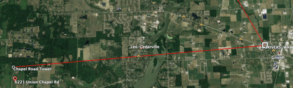
So let’s get to it. Our first image is out path. This link had clear line of sight from a 150-foot foot water tower to a 240-foot tower.


After getting out of the cold we let things burn in for a few days. This is what an initial spectrum analysis looked like.


As you can see the RSSI was within 2 DB, which isn’t terrible. However, due to interference, the MCS rates are markedly different, which is what results in the big differences in speed. Please note this is only with one radio enabled and on a 20mhz channel. We fully expect bigger speeds once we up channel sizes and enable the second radio.

Some stat screens from a cambium 550. This is a short hop. Less than a mile.


The following are results from a series of tests of AGLcom’s parabolic dish antennas on an existing link that is 5.7 miles long. The link typically passes 80-90Mbs with a TX capacity of 140 Mbs and radios used are Ubiquiti AF5X operating at 5218 Mhz. A full PDF with better Readability can be downloaded here..
The tests were taken in stages:
The tables below do not follow the test order as the third line of data was actually the last test performed.
Antennas:
A-Jirous JRC-29EX MIMO
B-Jirous JRC-29EX MIMO C-AGLcom – PS-6100-30-06-DP D-AGLcom – PS-6100-29-06-DP-UHP
Results:
Table 1 is the signal strength results of the various dishes on the link. The first line, A-B, is the original Jirous to Jirous. A is the first two columns of the link and are the A side and the last two columns are the B side on the link. What is of interest is that exchanging B to C in the second line brought the signal deviation between the channels to only 1db and 0 db as seen in Table 2. The third line was a result of replacing the horn on the A dish and optimizing the setting on the AF5X radios. This changed the signal by around 7db and improved the link capacity, Table 3. Clearly, the A dish had a problem with the original horn.
In the fourth line, D-B, the signal strength improved as well at the signal deviation on the two channels, Table 2 first two columns. This link was not optimized. The fifth line, D-C is both AGLcom dishes which improved the bandwidth, Table 3, and the signal deviations, Table 2. The final line, D-C, was the previous line optimized. The signal strengths moved closer together and the bandwidth improved.
Link Ch0 Ch1 Ch0 Ch1
A*-C -64 -66
D*-C -60 -60
-70 -74 -71 -71 -65 -66 -59 -59 -58 -58 -61 -61
Signal Strength (* optimized data) Table 1
Table 2 has four data columns, the first two being the measured results and the latter two being the measured difference from theory. The Jirous and AF5X calculators were used for the theory signals. Clearly the signal approached the theoritical limit with the optimization and with the change of dishes. The optimization improved the signal by ~9db for the link that we replaced the horn on the Jirous and by ~2db for the AGLcom link.
Link dSig dSig A-B 3 4 A-C 1 0 A*-C 2 1 D-B -1 0 D-C 0 0 D*-C 0 0
dSig dSig -16.5 -17.4 -17.0 -15.0 -8.0 -9.0 -13.3 -5.3 -7.0 -4.3 -5.0 -6.0
Signal strength variation from theory Table 2
The band width improvement was more obvious, Table 3, from 22 Mbs to 39 Mbs for the RX and 144 Mbs to 141 Mbs TX for the link with the horn replacement. The bandwidth improvement for the optimization of the AGLcom link was from 61Mbs to 66Mbs RX and from 211Mbs to 267Mbs for TX.
The bandwidth improvement from the original, optimized link to the AGLcom link is from 61Mbs RX to 67Mbs and from 210Mbs TX to 267Mbs. There is a clear improvement for the AGLcom link over the Jirous link.
Link BW-RX
A*-C 60.9
D*-C 66.6
BW-TX 144.6 141.4 210.0 211.0 215.0 267.6
Table 3
Conclusions:
The data supports a measurable improvement in both signal strength and bandwidth with the use of the AGLcom dishes. However, it is difficult to quantify the improvement. The Jirous dishes were identical whereas the AGLcom dishes were not. One of the jirous dishes was under performing initially but was repaired for the last tests. Additional testing is needed to provide accurate data analysis and performance comparison. The best performance tests would involve identical AGLcom dishes, ideally two links, one each of both types of dishes.

Recently we had a teaching moment for a couple of folks who had not had much experience with aligning higher frequency antennas with very tight beamwidths. This particular day we were aligning 2 foot Siklu 80GHZ antennas.
One of the questions we often get asked is how do you align these? These questions are usually asked by someone who is familiar with aligning 5ghz antennas with a 10 or 20 degree beam which you can eyeball and has tried a microwave shot. They find out it is much harder. The higher you go in frequency the tighter and smaller the beam is. Distance also affects how far off you can be. Think of it as a laser pointer. If you have ever taken a laser pointer out at night and shone it a long distance you will notice even the slightest movement will cause it to jump inches, even feet. Keep laser pointer analogy in mind for this next section.
In order to understand alignment, we need to understand lobes on an antenna. An antenna is just a device that focuses radiation in a direction. In a licensed microwave setup, these antennas focus the radiation in a tighter “beam”. Let’s go back to our laser pointer analogy. Some laser pointers project a smaller dot at 10 feet than others. Same for antennas. The diagram below shows what is called the main lobe and the side lobe.

The way to get the best signal is to get both dishes locked on to the main lobe. Sounds easy right? With higher frequencies, you are talking about millimeter waves. This means the main lobe may only be 3mm wide, about the size of this text on a laptop screen. Now imagine trying to keep that 3mm beam in the center of a paper plate at a mile. On top of that, the difference between the main lobe and locking onto a side lobe could be the difference of 1-2mm. A slight wind can move a dish 2mm.
To give you a real-world example. A 2ft 23 GHz antenna having 3 dB beamwidth of 1.6 degrees. Allowing for a path length of about 2.5 miles (this is licensed 23GHZ) the actual beamwidth at the receiving antenna is around 370 ft and is, therefore, likely to be greater than the height of the tower. If the antenna’s out of horizontal by even a couple of degrees to start, the antennas will miss by around 460 ft and not be able to “see” each other. This can be amplified as frequency and distance increase.
This is all fine and dandy, but what about the practical world? How do I align the thing?
It all starts with the FCC path coordination paperwork you will receive on your licensed link. There is a wealth of information in here. It tells you all of the following:
-Your mounting height (this is typically already known)
-Your heading (more on this in a bit)
-The antenna angle downtilt or uptilt (very important)
-The expected signal target
Armed with this information you will have all of the information you need to align the link. From this point, the philosophical side of things kicks in. Some tower climbers are good with using a compass to get their exact bearings. Others have high dollar tools to do it all via GPS such as microwave path alignment from Sunsight.
What everyone doing alignment should have in their toolkit are the following:
-A small magnetic bubble Level. We want to make sure we start with a level mount. We would be fighting an uphill battle if the pipe or standoff we are mounting to is not level.

-An angle Finder is very helpful for determining the antenna down or uptilt per the path calculation.

Obviously, the above tools are just one of many examples. There are more expensive ones and bare bones ones. Tools are only as good as the person using them.
-Ratcheting wrenches for the left and right and up and down adjustments.
Having ratcheting wrenches makes fine-tuning a very easy process. You will see why later.
-A good hands-free communication method. Depending on the tower FM communications may or may not work. Cell phones may or may not work. Being able to talk to the crew on the other end is crucial. And yes, to make this smooth you want a crew on the other end.
Aligning backhauls, especially microwave, is a skilled trade. With any skilled trade, you will get all kinds of tips and tricks of the trade. Some you may use, others you may not. Ask any Carpenter, Drywaller, or Mason and they will tell you little tips and tricks. They probably all are great and will work, but you may only use some of them. I am going to tell you mine. You may find others you like better.
We always start with a google earth plot of the path. I call this Phase 1. The goal of phase 1 is to get the radios talking. We make sure the line is exactly on the two points, not just approximate. If the backhaul it on the left side of the tower, we draw the line to/from the left side of the tower. We then pick 2-3 landmarks along the path as we can. We start with something close to the tower the climber should be able to see.

In our photo above we have picked out two reference points close to the tower the climber can see. The first is the clump of trees on the climbers left. The path passes “just to the right” of the edge of the end of the trees. The second reference is the intersection of the county roads about 2-3 miles out. Our path should be just to the right of those. That point of reference is more of a sanity check. More than anything. The climber at the other end has a similar printout. I have found communication during this process works best if both climbers and someone logged to at least one radio on the ground with a laptop are on a conference bridge. Many radios have lights, tones, or multimeter outputs to indicate signal. Some modern radios only have web-interfaces and apps. Hold a phone while trying to align can be cumbersome. This is where the guy on the ground can take some load off what the climbers are doing.
Regardless of the mechanics of the radio, the goal of Phase 1 is to establish a radio link, no matter how bad it is. Now, here is where the real meat and potatoes of backhaul alignment come into play. This is a very deliberate and calculated process. Your goal at the end of the entire alignment process is to end up with the following diagram

What many folks don’t realize is it is possible to establish a signal on a side lobe. So how do you know if you are on a side lobe? Here is how we start phase 2. This is what I call fine-tuning. Real original huh? Depending on good, or lucky you were during phase 1 you may have a long way to go or a short way to go to meet target. Remember that in your paperwork we talked about earlier? One side and one side only starts moving their fine adjustment on their antenna to the left and right and up and down. This is typically called sweeping. The key thing to note here is you need to find the very edges of the radio signal, not just the lobe you happen to be on.
Let’s take a real-world example to explain how sweeping affects main and side lobes. At the start of this article, we mentioned an 80ghz link. With our phase 1 rough alignment, we were able to get linked at a -86. The target was a -32. The first side to start alignment started sweeping to the right, signal started going from a -86 down to a -72 rather quickly. This was using very small turns of the adjustment. The ratcheting wrench was only clicking 1-2 times for each 2-3 db of signal change. Once it reached a -72 it started climbing back up. The climber then kept going to the right to find the edge of the signal, not just the lobe we were on. The signal started getting worse until we were back into the upper 80’s.

Now, the climber brings the alignment back to the left, and stops at the -72 and makes a mental note of where that is in relationship to the overall placement of the dish, etc. Some mounts have distinct notches, some guys use markers, others just remember. Now the climber continues on to the left and the -72 gets worse and goes back down to the -86 and continues to get worse. So the climber, at least for now, has found the sweet spot for the left and right alignment. The climber also knows this will probably change, but has found it for now. Climber repeats the same procedure for the up and down. Due to the anglefinder, the climbers have with them they feel pretty confident they are fairly close with the up and down so they do not adjust the up and down travel as much as the procedure goes on.

Next, the other side does the same procedure the first side did. They do the left to right and get the signal down to a -62. Essentially, what the climbers are trying to do is find the center, which will contain the strongest signal, by sweeping past the other signals. Keep in mind there may be only millimeters separating these other lobes. Due to physics, and the shape of the signal, the first lobe is actually stronger than the edges of the main beam.
Say what? The first lobe is stronger than the edges of the main beam? Yes, but not stronger than the main beam. Let’s go back to our installers. They have each had a go around at alignment and are only at a -62. On a 5ghz backhaul that would be respectable, depending on your noise floor. But we are 30db away from our target of -32. Some climbers, incorrectly I might add, try to do a shortcut by scanning in an x pattern instead of x and y-axis separately. This makes it easier to lock onto a side lobe.

So now our first climber goes back to making the left and right adjustments. At this point, the installer finds something odd. He has gotten the signal down to a -55, but that’s the best he can do. Even a small turn jumps the signal up Then our installer remembers the above statement. The first lobe is always stronger than the edges of the main beam. He gets the signal back down to a -55 and turns the alignment over to the other side.
Here is a very important thing to note. Both of our installers have now “gotten a feel” for the few turns needed to adjust the signal on these dishes. To them compared to 5ghz dishes, these are very tiny and almost insignificant movements. But they sure make a difference in signal. Now our installer at tower B has his second alignment session. As he is making adjustments the signal is not changing. He is moving his wrench for what seems like forever and the signal is barely moving, Any other time their signal would have been a -90 or dropped. What has happened here? The main lobe of one side has locked onto the first lobe because it is always stronger. Since the main lobe is bigger it seems like it takes forever to make any change. If we had a guy on the laptop he was probably also probably seeing very mismatched data rates. One side was probably much higher than the other by a large margin.
Then boom, all of a sudden the signal goes from a -55 to a -42. A 17 db jump! We can now tell we are on the main lobe. If the laptop person looks at the data rates now they should be more balanced.

At this point, it is just a simple matter of each side making finer and finer adjustments back and forth to get the signal down. If you think of the above circle/crosshair you are making smaller and smaller adjustments to nudge toward the center of the circle. This is where the ratcheting wrenches help by giving a very measured amount of travel. This helps with the whole feel of alignment. Much of it is feel to see how much you can move the adjustment mechanisms to make the numbers move. Sometimes it may be a single click of the wrench. Sometimes it may be one or two. It just depends. As you get closer and closer to target you are moving the adjustment less and less.
As you get closer and closer to target you need to be thinking about how tightening down the adjustment bolts will affect the alignment. Even tightening them down snug can affect the signal. That extra amount movement to tighten them down can move them slightly past their alignment center. You may need to take into account the amount of travel it takes to tighten down the adjustment bolt into account on smaller dishes. If it takes a half turn of the bolt to get it tight you may need to stop a half turn and tighten “into” target. As you tighten it down fully that is where you end up in align. If you wait until you are in align and then snug it completely down, the force of snugging it down may pull it past and you will end up with a worse signal.
This article sprinkled in some examples from a real-world install, with some theory, with some practical knowledge. Your mileage and experience will vary. Your experience with 6ghz vs 80ghz will vary as well. Each frequency will have it’s own quirks and tricks.
Couple of b5s in there too. All going up on some buildings in downtown Indianapolis.


You must be logged in to post a comment.