Recently, there have been some discussions on Facebook about waining support for 2.4GHZ . KP Performance recently published a Future of 5GHZ and beyond blog post. So why all this focus on 5GHZ and why are people forgetting about 2.4?
To answer this question, we need to update our thinking on the trends in networks, not just wireless networks. Customers are demanding more and more speed. Network backbones and delivery nodes have to be updated to keep up with this demand. For anything but 802.11 wifi,2.4GHZ can’t keep up with the bandwidth needs.
One of the significant limitations of many 2.4 radios is they use frequency-hopping spread spectrum (FHSS) and/or direct-sequence spread spectrum (DSSS) modulation. Due to 2.4GHZ being older, the chipsets have evolved around these modulation methods because of age. When you compare 2.4GHZ to 5GHZ radios running OFDM, you start to see a significant difference. In a nutshell, OFDM allows for higher throughput. If you want to read all about the differences in the protocols here ya go: http://www.answers.com/Q/Difference_between_ofdm_dsss_fhss
Secondly, is the amount of spectrum available. More spectrum means more channels to use, which translates into a high chance of mitigating interference. This interference can be self-induced or from external sources. To use an analogy, the more rooms a building has, the more simultaneous conversations can happen without noise in 2.4GHZ we only have 3 non-overlapping channels at 20mhz. Remember the part about more and more customers wanting more bandwidth? In the wireless world, one of the ways to increase capacity on your APs is to increase the channel width. Once you increase 2.4 to 30 or 40 MHz, you do not have much room to deal with noise because your available channels have shrunk.
One of the biggest arguments in support of using 2.4GHZ for a WISP environment is the physics. Lower frequencies penetrate trees and foliage better. As with anything, there is a tradeoff. As the signal is absorbed, so is the available “air time” for transmission of data. As the signal travels through stuff, the radios on both sides have to reduce their modulation rates to deal with the loss of signal. Lower modulation rates mean lower throughput for customers. This might be fine for customers who have no other choice. This thinking is not a long term play.
With LTE especially, the traditional thinking is being uprooted. Multiple streams to the customer as well as various paths for the signal due to antenna stacking are allowing radios to penetrate this same foliage just as well as a 2.4 signal, but delivering more bandwidth. These systems are becoming more and more carrier class. As the internet evolves and becomes more and more critical, ISPs are having to step up their services. The FCC says the definition of broadband is at least 25 meg download. A 2.4 radio just can’t keep up in a WISP environment. I am seeing 10 meg becoming the minimum customers want. Can you get by with smaller packages? Yes, but how long can you maintain that as the customer demand grows?
So what is the answer? Cell sizes are shrinking. This is helping 2.4 hold on. The less expensive radios can be deployed to less dense areas and still provide decent speeds to customers. This same trend allows 5GHZ cells to be deployed as well. With less things to go through, 5GHZ can perform in modern networks at higher modulation rates. Antenna manufacturers are also spending R&D to get the most out of their 5GHZ antennas. More money in the pipeline means stronger products. My clients are typically deploying 3.65 and 5GHZ on their towers. LTE is changing RF WISP design and taking the place of 2.4 and 900.
One of the problems installers run into on a few networks we manage is having the right tools to properly test a new install. Sure, an installer can run a test to speedtest.net to verify customers are getting their speed. Anyone who has done this long enough knows speedtest.net can be unreliable and produce inconsistent results. So, what then? Or what happens if you need to by-pass customer equipment easily? Most installers break out their laptop, spend a few minutes messing with settings and then authenticating themselves onto the network. Sometimes this can be easy, other times it can be challenging.
I have taken Lorenzo’s idea and have several different versions based upon the network. In most of our scenarios, the ethernet ports are what plug into the CPE or the customer’s equipment, and the technician connects to the mAP over wifi. This post covers using the mAP as an installer tool, not a traveling router. Lorenzo covers the travel option quite well in his presentation.
In this post, we focus on networks which use PPPoE. PPPoE networks usually are the ones who take much time to set up to diagnose. What we have done is set up an uncapped user profile that is available on every tower. Authentication can be done with local secrets or via radius. Depending on your IP design the user can get the same IP across the network, or have an IP that assigned to this user on each tower/routed segment. We could do an entire article on IP design.
On our Mikrotik, we setup ether1 to have a PPPoE client running on it. When the installer plugs this into the customers CPE the mAP will automatically “dial-out” and authenticate using the technician user we talked about earlier. Once this connection has is established, the mAP is set to turn on the red “PoE out” light on the mAP using the following code.
Note. Our PPPoE interface is the default “pppoe-out1″ name. If you modify this, you will need to modify the led setup as well to match.
The red light gives the technician a visual indicator they have authenticated and should have internet. At the very least their mAP has authenticated with PPPoE. There are netwatch scripts mentioned in the above presentation which can kick on another LED indicating true internet reachability or other functions. In our case, we can assume if the unit authenticates with the tower, then internet to the tower is up. While this isn’t always the case if the Internet is down to the tower you quickly know or the NOC quickly knows. At least you hope so. We chose the PoE out led because we are not using POE on this setup and a red light is noticeable.
Once the technician has a connection they can connect to an SSID set aside for testing. In our case, we have set aside a “COMPANY_TECH” SSID. The tech connects to this on their laptop, and they are online. Since this is a static profile, you can set it up just like a typical customer, or you can give the tech user access to routers, APs or other devices. Our philosophy is you set up this SSID to mimic what a customer account experiences as closely as possible. It goes through the same firewall rules and ques just like a typical customer.
To further enhance our tool we can set up a VPN. This VPN can is accessible from the laptop with a second SSID named “COMPANY_VPN”. Once the technician switches over to this SSID they have access, over a preconfigured VPN on the mAP, to the network, from where they can access things customers can not, or at least should not be able to access. Many modern networks put APs, and infrastructure on separate VLANs not reachable from customer subnets. The VPN comes in handy here. You can access these things without changing security. If you plan on using this router internally, the type of VPN you choose is not as important as if you plan to modify the config so you can travel as is the case with the above MUM presentation. If you plan to travel an SSTP VPN is the most compatible. If it’s just inside your network, I would suggest an l2tp connection with IPsec.
Our third configuration on this is to set up the second ethernet port to be a DHCP client. This setup is handy for plugging into the customer router for testing or for places where DHCP is the method of access, for example, behind a Baicells UE. If your network does not use PPPoE, you could have one ethernet be a DHCP client, and the other be a DHCP server. We have found having the technicians connect wirelessly makes their lives easier. They can plug the unit in and not have to worry about cables being too short, or getting behind a desk several times to plug and unplug things.
So why go through all this trouble?
One of the first things you learn in troubleshooting is to eliminate as many variables as you can. By plugging this into your CPE, you have a known baseline to do testing. You eliminate things such as customer routers, customer PCs, and premise wiring. The mAP is plugged directly in CPE, whether it be wired or wireless. Experience has shown us many of the troubles customers experience are traced back to their router. Even if you provide the router, this can eliminate or point to that router as being a source of the problem if a technician needs to visit the customer.
Secondly, the mAP allows us to see and do more than your typical router. From the mAP we can run the Mikrotik bandwidth test tool from it to the closest router, to the next router inlines, all the way out to the internet. A while back I did an article titled “The Problem with Speedteststs“. This article explains many of the issues testing just using speedtest.net or other sites. Being able to do these kinds of tests is invaluable. If there are four Mikrotik routers between the customer and the edge of your network all four of them can be tested independently. If you have a known good host outside your network, such as the one we provide to our clients, then you can also test against that.
Having a Mikrotik test tool like this also allows you access to better logging and diagnostics. You can easily see if the ethernet is negotiating at 100 meg or a Gig. You can do wireless scans to see how noisy or busy 2.4GHZ is. You have easy to understand ping and traceroute tools. You also have a remote diagnostic tool which engineers can remote into easily to perform tests and capture readings.
Thirdly, the mAP allows the installer to establish a good known baseline at the time of install. You are not reliant on just a CPE to AP test, or a speedtest.net test.
How do we make this portable?
You may have noticed in my above pictures I have an external battery pack hooked up to my mAP. I am a fan of the Anker battery packs
Distributors such as ISP Supplies and CTIconnect have the mAP.
Finally, you will need a USB to MicroUSB cable
If you want you can add some double sided tape to hold the mAP to the battery pack for a neat package. I like the shorter cable referenced above in order to have a neat and manageable setup.
No matter what gear you use for delivering Internet to your customers, the mAP can be an invaluable troubleshooting tool for your field staff. I will be posting configs for Patreon and subscribers to download and configure their mAPs for this type of setup, as well as a road warrior setup. In the meantime, we do offer a setup service for $200, which includes the mAP, battery, USB cable and customized configuration for you.
This post is a huge shout out to Tasos Alexiou from RF Elements. This story started out at WISPAPALOOZA Vegas this year. I had a few clients who have been fighting noise issues. While working the Cambium booth we would go over the benefits of ePMP for noise mitigation. This would naturally lead to an antenna discussion. You can’t have an antenna discussion without mentioning RF Elements and their horn design. As with anything, clients are skeptical to things outside the conventional way of doing things. It’s not that the client is closed minded, but change becomes a little harder when revenue and cash outlay are involved. I am a very visual guy so I walked several of these clients over to the RF Elements booth so they could see the product and have it explained by the folks themselves.
These clients were getting it, but I could tell they were a little hesitant to make the leap. This is where the teamwork of the story really comes into play. Tasos could sense the same thing I was seeing, and came up with a plan. In the shipment of their gear to Vegas, they had some extra gear. After some negotiation, he told us to stop by after the show and he would see what he could do to get some gear in the hands of both of these clients. After the show, I was able to send both of these clients home with some 30 and 45-degree horns. Not only that, but these clients were able to talk about their specific situations, draw diagrams, and get a great understanding of how to get the best fit out of the equipment.
I am happy to say we have the first results from these horns. Mohave Broadband was able to put up a 30-degree horn in an area where they were having clients with signal and interference issues. By adjusting their 90/120 sectors, which even have beamforming, they were able to have the horn fit in their most troublesome area. Some of the troubles were customers who could not connect on a certain frequency very well, but others could. If the frequencies were changed the good customers became bad and vice versa. Once the horn was in place we noticed a couple of things.
The first was customers in the 30-degree beam of the horn were able to connect at good signals and data rates. These were customers who were pointed right at the sectors before, not ones on the fringes.
Secondly, due to the nature of the horn we were able to select from more channels due to the lack of sidelobes from the horns.
Customer links on the AP.
We could go on and on how the ePMP 2000 APs with their noise filtering, and the “clean” pattern of the horn make the difference but that is not the focus of the article. The focus is how many separate pieces of the WISP community came together to help. From WISPA putting on the show to the willingness of Tasos and RF elements to help these customers, and the ability to sit down and draw out diagrams and antenna placement to get the best place to place antennas. For those of you who don’t attend tradeshows, this is one of the success stories with a few more to come on this blog.
Recently we installed a PTP 550 link for a client. This is a connectorized version with 2-foot dishes on it for a four-mile link. Overkill you say, but the idea is the dishes make up the gain and not transmitter power. A much cleaner signal can be achieved which falls within the FCC guidelines for total EIRP.
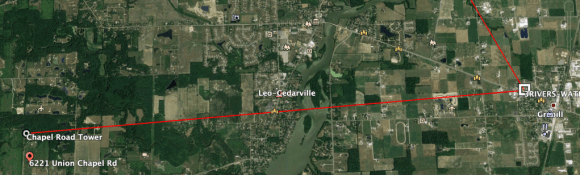
So let’s get to it. Our first image is out path. This link had clear line of sight from a 150-foot foot water tower to a 240-foot tower.
Google Earth PathThe 240 Foot tower150 Foot water tower
After getting out of the cold we let things burn in for a few days. This is what an initial spectrum analysis looked like.
Radio Frequency set on 5820 mhzRadio Frequency set on 5200mhz
As you can see the RSSI was within 2 DB, which isn’t terrible. However, due to interference, the MCS rates are markedly different, which is what results in the big differences in speed. Please note this is only with one radio enabled and on a 20mhz channel. We fully expect bigger speeds once we up channel sizes and enable the second radio.
A discussion which comes up over and over in the WISP space is grounding and proper installation of customer CPE. The folks at perfect-10 (https://www.perfect-10.tv/) were a vendor at #WISPAPALOOZA2018. One of the best things I have seen them in a long time is the below photo they created. This is a great illustration of how a proper CPE goes.
From: https://www.icann.org/resources/pages/ksk-rollover/#overview
ICANN is planning to perform a Root Zone Domain Name System Security Extensions (DNSSEC) KSK rollover as required in the Root Zone KSK Operator DNSSEC Practice Statement [TXT, 99 KB].
Rolling the KSK means generating a new cryptographic public and private key pair and distributing the new public component to parties who operate validating resolvers, including: Internet Service Providers; enterprise network administrators and other Domain Name System (DNS) resolver operators; DNS resolver software developers; system integrators; and hardware and software distributors who install or ship the root’s “trust anchor.” The KSK is used to cryptographically sign the Zone Signing Key (ZSK), which is used by the Root Zone Maintainer to DNSSEC-sign the root zone of the Internet’s DNS.
Maintaining an up-to-date KSK is essential to ensuring DNSSEC-validating DNS resolvers continue to function following the rollover. Failure to have the current root zone KSK will mean that DNSSEC-validating DNS resolvers will be unable to resolve any DNS queries.
If you are running bind the quickest way to check is this:
If your configuration shows dnssec-validation yes;, you must change it to dnssec-validation auto;and restart your server before taking the steps below. This is in your named.conf
Dubbed BaiEPC, the solution will be available in two forms – Standard and Professional. The Standard version is designed for small to mid-sized networks, while the Professional version is designed for larger networks and provides smaller companies an expansion path as their businesses grow.


You must be logged in to post a comment.