Recently, we had a client question why we didn’t mount antennas higher up on a tower with an FM repeater on it. The top of the tower has an FM repeater on it so we mounted the equipment about 25 feet below that.
When you are talking about antennas and transmitters the basic thing to remember is it’s all radiation. Good antennas have predictable drop off patterns and, when paired with a good transmitter, have crisp frequency drop offs. However, there is still radiation emitting from feedline and the antenna on the tower. Many FM repeaters use a dipole design. Some are folded, others are different types. Below is an antenna pattern from a Dipole antenna.
As you can see there are a few patterns radiating from the antenna. These patterns should be taken into consideration when mounting your equipment near FM, UHF, or VHF systems. Radiation may interfere with things such as your cat-5, or your PIM. In an earlier article, I talk about low-pim cables and what affects PIM. This is very important when you are deploying LTE gear. RF radiation from high power transmitters can cause PIM issues if the wavelength happens to coincide with the wavelength of the other transmitter. This does not mean they are on the same frequency. Remember, in RF you have full wave, 3/4,1/2, and 1/4 wavelengths to deal with.
Other things to consider are near and far field patterns. If you want some heavy reading you can read about it on Wikipedia.
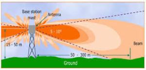
Our next issue and the most common issue is the radiation getting into our Ethernet cables as well as our radios on the tower. Below illustrates the propagation of signals coming out of an antenna on the top of the tower. If you notice, some of the radiation is directed underneath of the antenna. Any equipment mounted too close underneath will be bombarded with radiation.
Too much radiation can cause link negotiation issues, signal degradation, and other issues. By moving our antennas out of the patterns of other antennas we can make for a more reliable system. This is one case where higher on the tower is not always better. Just because another antenna is not mounted in front of another it does not mean they are in each other’s radiated patterns.
The Occupational Safety and Health Administration and the Federal Communications Commission are concerned about the risks faced by employees in the communication tower industry. Employees climb communication towers to perform construction and maintenance activities and face numerous hazards, including fall hazards, hazards associated with structural collapses and improper rigging and hoisting practices, and “struck-by” hazards.
As the number of WISP LTE deployments increase, there are many things WISPs will need to be mindful of. One such item is properly supporting antenna cables. LTE systems are more sensitive to cable issues. In a previous blog post, I talked about pim and low-pim cables. One of the things that can cause low pim is improperly mated cables. If cables are not supported they can become loose over time. Vibration from equipment or even the wind can loosen connections.
How do we support cables?
We can take a cue from the cellular industry. The following are some examples of proper cable support. Thanks to Joshua Powell for these pics.
Supporting Hardline connectors
Where can you get these?
A good place to start are sites like sitepro1 or Tessco has a selection.
So the next time you are planning your LTE deployment think about cable support.
One of the topics that came up during the Baicells troubleshooting tips was the notion of PIM testing, and cables which are PIM rated.
PIM sweeps are a common thing in the Cellular field. One of the first questions folks often ask is what is a PIM sweep? If you think of PIM testing as a passive test and line sweeping as an active test that is a good start. PIM testing looks for problems with things like connectors, cables, and other “layer 1” items.A PIM test is not a line sweep. Line sweeping measures the signal losses and reflections of the transmission system. this is typically VSWR.A line sweep is an active test. It can not detect the same things a PIM test can.Many HAM radio folks are familiar with a line sweep where the reflected power is measure in an antenna system. In a line sweep you deal with reflected power and all that.
What does a PIM test do?
When you do a PIM test typical two high power signals are injected into the antenna line.You can actually pass a sweep test but not a PIM test.
I won’t go into PIM tests very much because you need high dollar units such as those from Anritsu and Kaelus. These cost 10’s of thousands of dollars new.Sometimes you can find these used.However, the next thing you will run into is understanding the output of such a device.Cell crews go to week long certification classes to become a PIM certified tech from Anritsu and others.
What causes a PIM test to fail?
According to Kaelus the most common problems are:
• Contaminated surfaces or contacts due to dirt, dust, moisture or oxidation. • Loose mechanical junctions due to inadequate torque, poor alignment or poorly prepared contact surfaces. • Loose mechanical junctions caused transportation shock or vibration . • Metal flakes or shavings inside RF connections. • Poorly prepared RF connections •Trapped dielectric materials (adhesives, foam, etc.) •Cracks or distortions at the end of the outer conductor of coaxial cables caused by over tightening the back nut during installation. • Solid inner conductors distorted in the preparation process causing these to be out of round or tapered over the mating length. • Hollow inner conductors excessively enlarged or made oval during the preparation process.
Why does cable matter?
Cables do not typically cause PIM, but poorly terminated or damaged cables can and do cause problems.
Cables with Seams can cause issues.The seam can corrode.Plated copper, found in cheaper cables, can break away from the aluminum core. This actually allows small amounts of flaking to happen between the connector and the core of the cable.This will cause PIM issues and is very hard to diagnose. Imagine little flakes inside a connector. You don’t see them until you break open the connector, and even then they may be pretty little flakes.
Cables can change their physical configuration as temperature varies. For instance, sunshine can warm cables, changing their electrical length. A cable that happens to be the right length to cancel out PIM when cool may show strong PIM after changing its length on a warm day, or, it can work the other way around, good when hot and bad when cold. In addition, the physical change in length can make a formerly good connection into a poor one, also generating PIM. Other environmental factors such as water in the connector or cable can be an issue, as with any RF setup.
I think I have PIM issues. What are some indications?
PIM often shows up as poor statistics from the affected antenna. One of the first and most direct indications of PIM can be seen in cells with two receive paths. If the noise floor is not equal between the two paths, the cause is likely PIM generated inside the noisy receive path.
How Do I prevent PIM issues?
Cable quality and connector quality are one of the biggest factors in the PIM quality of a LTE system.Many WISPs are used to making their own LMR cables and putting on their own connectors.There is a difference between a low PIM LMR-400 cable and normal LMR-400.Same for connectors.One of the recommendations today was to use 1/2” superflex heliax.
The easy recommendation is to buy pre-made cables that have already been PIM certified.In a typical WISP setup, you do not have lots and lot of components in your setup. Buy already certified components from your distributors that are “Low PIM rated”.
As more and more Wireless ISPs (WISPS) get into licensed microwaves, bigger antennas, and fiber up the tower (FUTT) they are getting into an arena typically reserved just for the Cellular and broadcast folks. This can result in an overwhelming amount of things to deal with.
If you are renting space on a commercial tower managed by a regional or national company such as American Tower (ATC) you will run into things like application fees, engineering studies, and closeout documents to just name a few. Once you have your notice to proceed (NTP), the real work begins.
During your negotiation phase, and in your contract, you should have a center line on the tower. This states the center line on the tower where your equipment is mounted. An example is if your centerline states 200, on most contracts that means you have something like 5 feet above that and 5 feet below that. Think of it as a window. You have a window of 195-205′ on the tower for your equipment to fit in.
Centerline example. Photo courtesy of Michael Pelsor
The equipment you put on the tower was specified in the engineering phase of the paperwork. Model numbers of mounts, antenna models, and all that are decided before the first piece of equipment is ever put on the tower. This is very important to adhere to because many tower companies will require a closeout procedure. This normally includes pictures of your equipment and how it’s mounted, pictures of what is called a tape drop, and other things.
Tape Drop Pic courtesy of Michael Pelsor
The sheer amount of things to think about on a commercial tower with multiple tenants could extend this blog post on for a long time. But, one of the biggest things to consider is when you are installing how your cable runs, antennas, etc. are in relationship to other equipment. Are your cables somewhere they might be stepped on by someone passing your equipment to get to theirs? Does your equipment cross mounts which may be removed later or modified?
In the second part of this series we will talk about some of the higher-end tools which may save you tons of time, thus paying for themselves rather quickly.
If you are like me and enjoy technical manuals here is a good one from Commscope for you installers out there. It is a good overall manual, with some Commscope specific products thrown in.
From the manual The Drop Cable Applications and Construction Guide is written for the cable installation professional who, due to the diverse services offered by CATV and telecommunication service providers, needs a quick and handy reference to practical installation information, especially in the case of retrofitting.
We’ve tried to simplify the decision-making process as to which cables to choose for what installation, taking into account factors such as performance over distance, preventing RF interference and fire/safety codes.
Steve Morris has taken all of his hard-earned lessons and put them all in one comprehensive book. It’s over 220 pages of facts, techniques, hardware and lots of answers to your tower construction questions.
Several clients have asked how to mount 1/2-1″ pipe to handrails or other such surfaces. Below are some beam clamps and conduit hangers. Our tip is to “pin” them by drilling some self-tapping screws to hold the pipe from spinning.
I have been wanting to write this article for awhile. When the topic is fresh in my mind I am usually too tired from a day of climbing. By the time things get around the lessons learned have escaped me. So, after a day of being in the sun on a 150 foot monopole I figured I would share some best practices. These are aimed toward the WISP who wants to maximize their climbs.
1.Tighten sector brackets on the ground and other bolts. If it is holding it to the sector tighten it. The idea is the climber wants to be able to position the antenna against the mounting pole as easily as possible without needing extra hands. Sometimes having both hands free is a challenge. If you want to adjust downtilt on the ground the following links can help speed up the process. This is not necessary nor is it a requirement. It just is one less thing to do in the air. Some helpful Links:
I am planning on another blog article about downtilt calculations and my thoughts. We will go into this in a future post.
2.For Wireless backhaul shots in the 0-7 mile range use google earth. Draw a line between the two points and use two reference points to get in the neighborhood. By looking at the below screenshot I know to align my path over the edge of the building almost at the base of the tower. This helped me determine mounting location and get a pretty close aim. You can get fancy with compasses, GPS alignment devices, and other high-tech toys, but people are typically visual people. Having a reference point is easier on the mind than having a number like 121 degrees off north. Microwave shots are a different beast so don’t lump tight beamwidth licensed links into the above statement.
3.Don’t get too hung up on labels. Instead I like to color code things. If I am putting up 3 sectors I will get some colored tape and label them with a blue piece, a red piece, and a green piece. This way if the client wants to have a sector facing north We have the software labeled blue. I can identify color and tell the ground crew I faced the blue sector north. Makes things easier in the high stress environment of being hundreds of feet in the air. The cellular companies have some standardized labeling of their sectors:
Alpha is the North FACING vertical antenna on the cell tower
Beta is the Southeast FACING vertical antenna on the cell tower
Gamma is the Southwest FACING vertical antenna on the cell tower
I would suggest come up with a SOP for all your tower deployments, but be flexible. Due to the various mounting locations it’s not always prudent to cookie cutter a WISP deployment like the cellular folks do. I have installed gear on towers where you have a small corner of a rooftop or grain facility. Due to other things being up there, the fact you are trading service or paying very little, your mounting options may be limited.
4.On a related note color code everything. If you use colored tape, make sure to match the ethernet cables going to the sectors. This way it is easier to identify the cable going to the sector. This also helps in easier identification of where things are plugged in.
5.There are six phases of the a WISP deployment.
Stage one- assembly and staging
Stage two – Mounting radio equipment and antennas
Stage three – Connecting power and connectivity.
Stage four – Physical adjustment and tuning
Stage five – Testing and tweaking
Stage six – cleanup and zip up
Think about each of these. This will be another future blog post.
6.Have a plan of action. Have a flexible order of doing things. Be able to adjust this on the fly due to various factors. Sometimes is makes sense to mount the sectors, backhauls, and any other boxes at the top. Once you have them mounted then make the connections. Other times it may make sense to run the cable when you mount the device.
7. Have a loadout of specific tools in a bucket or tool pouch. I like to include the following:
Knife – Automatic or assisted opening
Crescent wrench
Super-88 Tape
Zip ties
Phillips Screwdriver
Flat Screwdriver
Slip Joint pliers
Other tools such as ratchet wrenches, different sized tools, power tools, etc. are handy, and can make life easier. However, the above tools will allow you to 90% of what you need to do to install or remove most WISP equipment. The flat screwdriver can be used to pry things loose or for leverage.
8.If you can do it on the ground do it. Terminating and testing cat-5 is easier on the ground than 150 feet in the air.
9. Train the ground crew to think about how this affects someone on the tower. Most of the time folks don’t have the luxury of platforms. So they are hanging off the tower in awkward positions. Doing a pull with 3 sectors attached to a load line might seem like you are saving time, but it might make things complicated for the climber. Sometimes, 3 pulls might make their life easier. They only have to deal with one thing at a time. They aren’t fighting trying to unhook multiple antennas or figuring out what is what. This is where straps come in very handy. A strap allows a climber some extra flexibility to move things around and position them better.
10.Have a checklist of sorts. This can be a running thing as you go along. I routinely tell the ground crew to remind me to do this. If you have someone writing this stuff down they can read it back to you before you come down.
There are a great variety of tools, tricks, and ways of putting stuff on the tower. Many people have their own ways of doing things. These are just some of the best practices I have come up with through experience. We could debate tape vs zip ties and other things for hours. Please leave comments and some tips that make your life easier.


You must be logged in to post a comment.